| a. General bibliography
SOCIETY FOR UNDERWATER TECHNOLOGY. Advances in underwater technology,
ocean science and offshore engineering. Volume 5. Submersible Technology.
1st ed. Graham & Trotman, 1986.
SOCIETY FOR UNDERWATER TECHNOLOGY. Advances in underwater technology,
ocean science and offshore engineering. Volume 9. Stationing and Stability
of Semi-Submersibles.1st ed. Graham & Trotman, 1986.
UPSON, R. H. and KLIKOFF, W.A. Application of practical hydrodynamics
of airship design. NACA Report No 405, 1931.
SOCIETY FOR UNDERWATER TECHNOLOGY. Advances in underwater technology,
ocean science and offshore engineering. Volume 15. Technology Common to
Aero and Marine Engineering. 1st ed. Graham & Trotman, 1988.
WHICKER, L. F. and FEHLNER, L.F. Free stream characteristics of a
family of low aspect ratio all moveable control surfaces for application
to ship design. DTMB Report 933, 1958.
ABKOWITZ, Martin A. Stability and motion control of ocean vehicles.
1st ed. Massachusetts Institute of Technology, 1969.
BISHOP, R.E.D. and PRICE, W.G. The dynamics of marine vehicles and
structures in waves. 1st ed.
The Institution of Mechanical Engineers, 1975.
FAY, James A. Introduction to Fluid Mechanics. 1st ed. Massachusetts
Institute of Technology, 1994.
THE UNIVERSITY OF SALFORD. DEPARTMENT OF AERONAUTICAL, MECHANICAL, AND
MANUFACTURING ENGINEERING. Second Year notes in Flight Dynamics.
The University of Salford, 1998.
KINSKY, Roger. Applied Fluid Mechanics. 6th ed. McGraw-Hill Book
Company, 1982
CASINI, Giuseppe.Calcolo e disegno meccanico per disegnatori operai
e tracciatori. 9th ed.
Ulrico Hoepli Editore SPA, 1974.
MUCCI, Peter. Handbook for engineering design using standard materials
and components. 4th ed.
BSI Standards, 1994.
THE INSTITUTION OF PRODUCTION ENGINEERS. A guide to design for production.
1st ed.
The Institution of Production Engineers, 1984.
GRIFFITHS, A. Fasteners handbook. 1st ed. Morgan-Grampian Books
Ltd. 1969.
KERMODE, A. C. Mechanics of flight. 10th ed. Longman Group Limited,
1996.
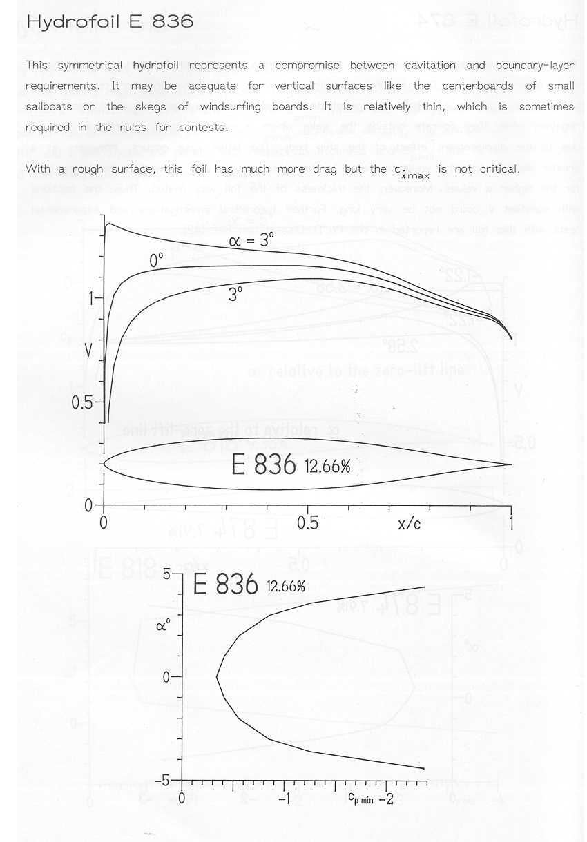
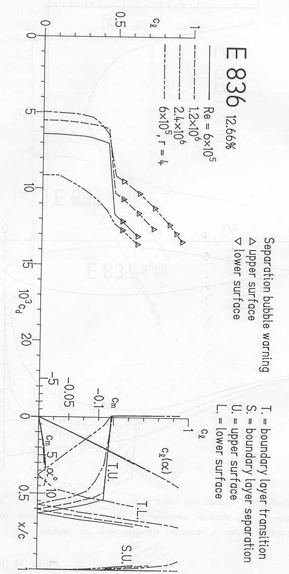
EPPLER, Richard. Airfoil design and data.1st ed. Springer-Verlag,
1990.
b. Regulations and Procedures:
NATIONAL OCEANIC AND ATMOSPHERIC ADMINISTRATION.
Section 8: Working Dive Procedures. Part 10: Diving from an anchored
platform.
NOAA Manual. Diving for Science and Technology.
<http://www.uwsports.com/reference_library/noaa/section_08/subsection_10.htm>
National Oceanic and Atmospheric Administration. (Last access: 17 May
2000)
BRITISH STANDARDS INSTITUTE. British Standards Service.
<http://bsonline.techindex.co.uk>
Technical Indexes Ltd. Issue 99-10. Oct 1999.
(Last access: 17 May 2000)
HER MAJESTYS STATIONARY OFFICE. Police Diving Manual. Her Majestys
Stationery Office, 1st ed. 1975. (Last access: 17 May 2000)
ER-ONLINE. Reference & Standard Organizations.
<http://www.er-online.co.uk/standard.htm>
Engineering Resources Online, 3 Oct. 1999
(Last access: 17 May 2000)
IBM. Intelectual Property Network
<http://www.patents.ibm.com/>
1st ed. IBM, January 1997
(Last access: 17 May 2000)
IBM. Gallery of obscure patents.
<http://www.patents.ibm.com/gallery>
IBM, Jan. 1997.
(Last access: 17 May 2000)
c. Online Sources:
MARINET. 1999 Ocean Technology Workshop <http://www.motn.org/workshop99/default.html>
MariNet: Marine Technology Online. Last updated: 29 Apr. 1999 (Last access:
17 May 2000)
ANDREW KING. Patent information. <http://unicorn.sanger.ac.uk/patent.htm>
The Welcome Trust Genome Campus home pages, 15 July 1999. (Last access:
17 May 2000)
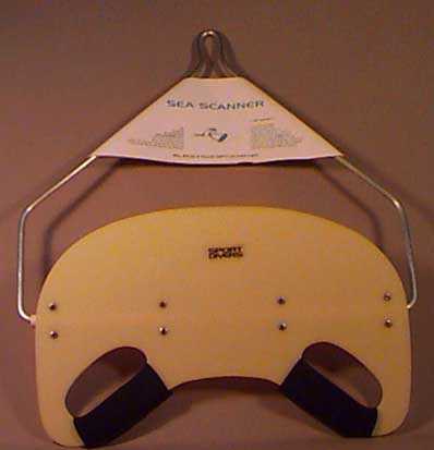
DISCOUNT DIVERS SUPPLY. Underwater Exploration. Sea Scanner.
<http://discountdivers.com/fx/explore1.html>
(Last access: 17 May 2000)
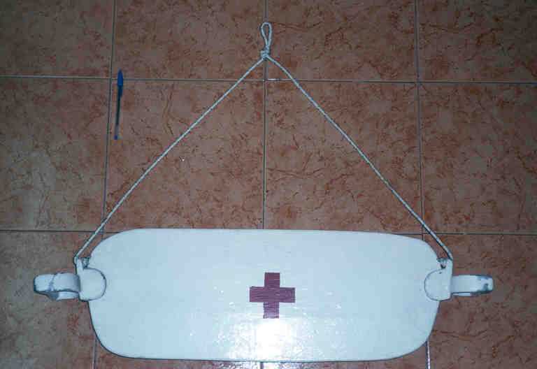
DISCOUNT DIVERS SUPPLY. Underwater Exploration. Underwater tow sled.
<http://discountdivers.com/fx/explore1.html>
(Last access: 17 May 2000)
DCF INNOVATIVE DESIGN. ROV Net. <http://www.rov.net>
DCF Innovative Design, 31 Oct. 1999
(Last access: 17 May 2000)
OCEANEERING INTERNATIONAL, INC. Oceaneering <http://www.oii-adtech.com>
Oceaneering International, Inc. 1999. (Last access: 17 May 2000)
BENTHOS Inc. Benthos, Underwater Technology. <http://www.benthos.com/benthos.htm>
(Last access: 17 May 2000)
ISR ORGANIZATION. International Submarine Races. <http://www.isrsubrace.org>
ISR Organisation, Foundation for Underwater Research and Education, 8 Oct.
1999 (Last access: 17 May 2000)
SEATRONICS. Sidescan Sonar Systems. <http://www.seatronics.co.uk/Side.htm>
Seatronics, Inc.
1st ed. 28 Feb. 1997 (Last access: 17 May 2000)
NETWORK WORK PLACE DESIGN. Waal Catalogue of products. <http://www.worcester-aluminium.com/product.htm>
1st ed. Worcester Aluminium Alloys, 1999.
(Last access: 17 May 2000)
JERGENS INC. Catalogue of products.<http://www.jergensinc.com/>
1st ed. Jergens Inc. 2000.
(Last access: 17 May 2000)
NET RESOURCES INTERNATIONAL. Offshore Technology. <http://www.offshore-technology.com/index.html>
1st ed. Net Resources International, 2000. (Last access: 17 May 2000)
UNIVERSITY OF WASINGTON, SCHOOL OF OCCEANOGRAPHY. The virtual mooring
glider. An autonomous underwater glider. <http://www.ocean.washington.edu/research/glider/project.html>
1st ed.
University of Wasington, 1998. (Last access: 17 May 2000)
DAVENPORT, Ryan. Davenport skeleton sleds <http://members.home.net/sleds>
Davenport skeleton sleds,
7 May 2000. (Last access: 17 May 2000)
Harding, Jeff. Scientific diving and boating safety program.
<http://www2.ucsc.edu/sci-diving>
Institute of Marine Sciences of the University of California, Dec. 1999.
(Last access: 17 May 2000)
MANCHESTER COMPUTING. Consortium of Academic Libraries in Manchester
TI web. <http://tiweb.li.umist.ac.uk/tisearch.htm>
Umist Library, Jan. 2000 (Last access: 17 May 2000)
d. Magazines and Catalogs:
CHAPLIN, TIM. Umbilicals. Underwater Contractor Magazine. Issue
8, Jan/Feb 1997
MARINE SONIC TECHNOLOGY LTD. Sea Scan? PC Side Scan Sonar.Oceanscan,
for Marine Sonic Technology Limited (MSTL). 21 Oct 1999 |